
In this guide 8 sections
Choose the wheel for its position and task
For a sintered-stone 45° edge, compare the incoming cut, machine station, removal allowance and final joint requirement before selecting a chamfering wheel. The listed metal-bond range serves front chamfering and the resin-bond range serves rear chamfering. Match the exact dimensions and station arrangement rather than selecting from the bond name alone.
Separate the miter geometry from its final finish
01Geometry and front stage
Check the incoming cut, angle, remaining edge and the front-station tool.
02Rear stage and joint fit
Review the finishing allowance, surface marks and fit of the completed joint.
Check the available configurations
| Product family | Diameter | Segment height × thickness | Bore | Position |
|---|---|---|---|---|
| Metal-bond diamond chamfering wheel | Φ130 / Φ150 | 8 × 8 mm | 12 mm | Front chamfering |
| Resin-bond diamond chamfering wheel | Φ130 | 10 × 12 mm | 12 mm | Rear chamfering |
| Resin-bond diamond chamfering wheel | Φ150 | 6 × 12 mm or 10 × 12 mm | 12 mm | Rear chamfering |
Compare the options Tap to expand
Metal-bond diamond chamfering wheel
- Diameter
- Φ130 / Φ150
- Segment height × thickness
- 8 × 8 mm
- Bore
- 12 mm
- Position
- Front chamfering
Resin-bond diamond chamfering wheel · Φ130
- Diameter
- Φ130
- Segment height × thickness
- 10 × 12 mm
- Bore
- 12 mm
- Position
- Rear chamfering
Resin-bond diamond chamfering wheel · Φ150
- Diameter
- Φ150
- Segment height × thickness
- 6 × 12 mm or 10 × 12 mm
- Bore
- 12 mm
- Position
- Rear chamfering
The 130 mm and 150 mm resin options have different listed segment combinations. Read the complete row for your diameter. Confirm the mounting and station arrangement against the actual machine before approving a replacement.
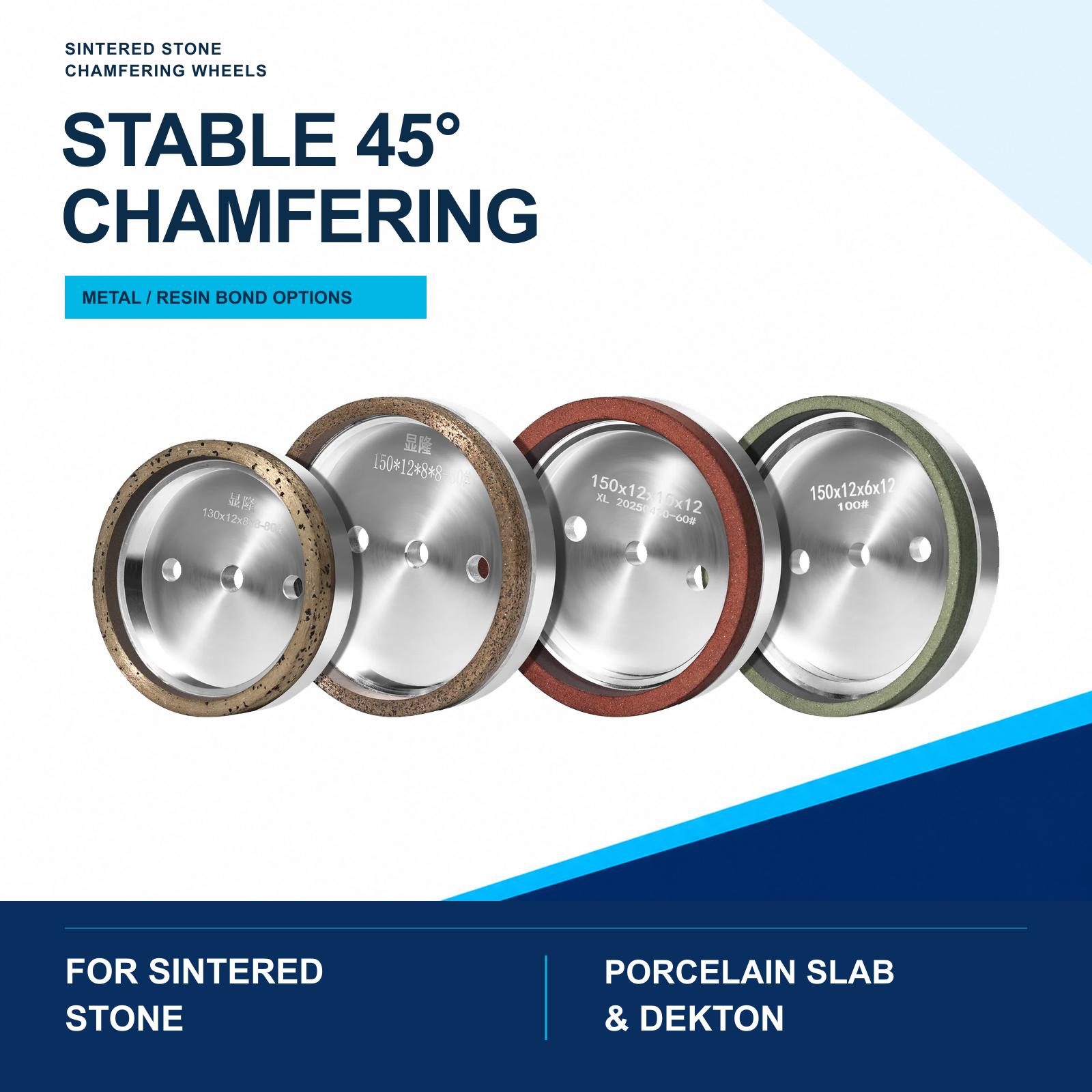
Sintered Stone Chamfering Wheels
The metal-bond options use the front position and the resin-bond options the rear position. Confirm the 45° beveling setup, 12 mm bore and working section for the selected diameter.
View specificationsInspect the primary cut first
A wheel receives the edge left by the cutting operation. Photograph the miter face and thin edge before the first chamfering stage. Existing chips, angle variation or an unstable cut can carry through later operations.
Use the slab manufacturer’s procedure for the material and thickness. Keep straight-cut and miter approvals separate. If the primary cut needs attention, use the sintered-stone chipping guide before changing the wheel sequence.
Follow the edge through the front and rear stages
Inspect the edge before and after each operation
- 01
Primary cut
Photograph chips and angle variation before the chamfering wheel touches the slab.
- 02
Front station
Check the metal-bond wheel, mounting and material left for the next station.
- 03
Rear station
Check the resin-bond wheel and whether earlier marks have been removed.
- 04
Joint inspection
Compare the finished edge and assembled fit against the approved sample or drawing.
At the front stage, inspect the incoming geometry, tool position and remaining allowance. At the rear stage, inspect whether earlier marks are being removed and whether the final edge remains within the required shape. Check the joint fit after the sequence rather than judging the wheel from surface shine alone.
Keep wheel identity and position with each photograph. A supplier can then distinguish an incoming-cut problem from a defect introduced at a particular station.
Selection example: choosing a 150 mm rear wheel
The resin-bond table lists 150 mm options with 6 × 12 mm or 10 × 12 mm segment dimensions and a 12 mm bore. Diameter and bore narrow the candidates, but the segment size must also suit the machine, contact and required allowance.
Send the current wheel dimensions and station photographs with the miter drawing. Ask the supplier to identify the proposed combination and its intended role. Compare the complete edge on the actual slab before adopting it for production.
Check setup before changing the specification
Inspect mounting, alignment, spindle condition, coolant delivery and work support using the machine instructions. A repeated scratch or chipped corner may follow an unstable setup even after the wheel changes. Record the position and timing of the defect.
If the machine and incoming cut are satisfactory, compare a suitable alternative under the same approved conditions. Norton’s grinding-wheel selection guidance identifies required finish, contact area and machine conditions as factors in wheel selection.
Prepare a focused wheel enquiry
Provide the slab product and thickness, machine model, front/rear station layout, current wheel dimensions and grit designation, and the required joint. Include photographs before and after the relevant stage. Those details help the supplier compare a standard configuration or discuss a suitable alternative without guessing from diameter alone.
FAQ
Is a metal-bond chamfering wheel always used before a resin-bond wheel?
Metal is commonly considered for shaping and resin for refinement, but the actual order must follow the machine design and approved product system. Confirm the intended position, workload and process with the tool and machine suppliers.
Can one wheel create the complete 45-degree edge?
It depends on the incoming cut, removal, machine and accepted edge. A low-removal process may use fewer stages, but a single wheel should not be assumed to provide both geometry correction and final refinement without a controlled trial.
Can the straight-cut settings be used for a 45-degree miter?
Do not assume so. Slab fabrication manuals often provide separate guidance for angled cutting. Follow the slab, tool and machine documentation and approve the miter process separately.
What should be checked before shipment?
Check wheel identity, approved revision, diameter, bore, agreed geometry, visible condition, quantity, front/rear station labels and protective packing. Application performance must still be verified during incoming inspection and the first controlled run.